ANSYS Intro
Updated:
유한요소법(Finite Element Method)는 대부분의 CAE Program들의 기본 이론으로 컴퓨터를 사용해 공학문제의 수치해를 근사적으로 구하는 방법이다. 과거에는 Solid mechanics, Structural analysis에서 사용되었지만, 현재는 열전달, 유체역학, 진동, 전자장 등 거의 모든 공학 분야에서 사용하고 있다.
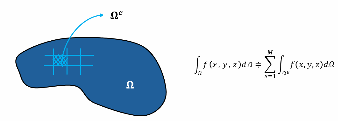
유한요소법은 해석 영역을 위한 유한 요소로 분할하여 해석 모델(유한 요소 모델, Finite Element Modeling)을 만든다. 여기서 유한요소(Finite Element)는 기하학적인 형상을 갖는 작은 요소를 의미한다.
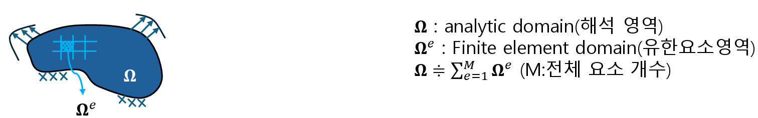
유한요소법의 기본 개념은 다음과 같다.
원의 면적을 예로 들면 다음과 같다.
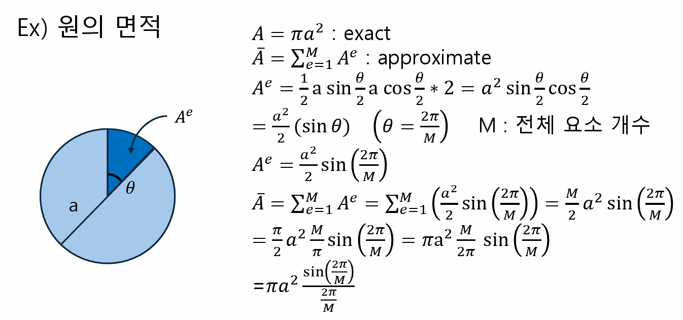
요한요소해는 요소의 개수에 따라서 오차가 달라진다. 즉, 전체 요소 개수(M)를 무한대로 하면, error는 0으로 수렴한다.
Finite Element 종류
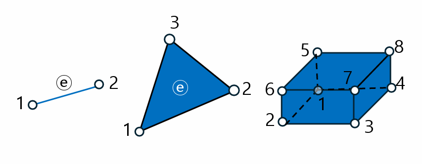
형상(Shape)에 따라 분류하면 다음과 같다.
- One dimensional element
- line element, bar, beam element
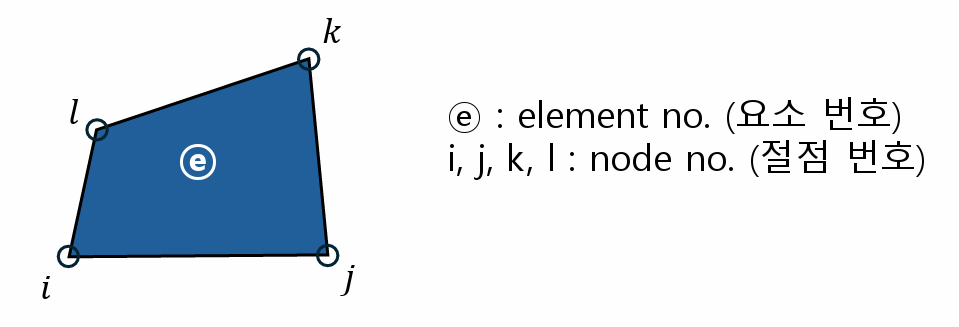
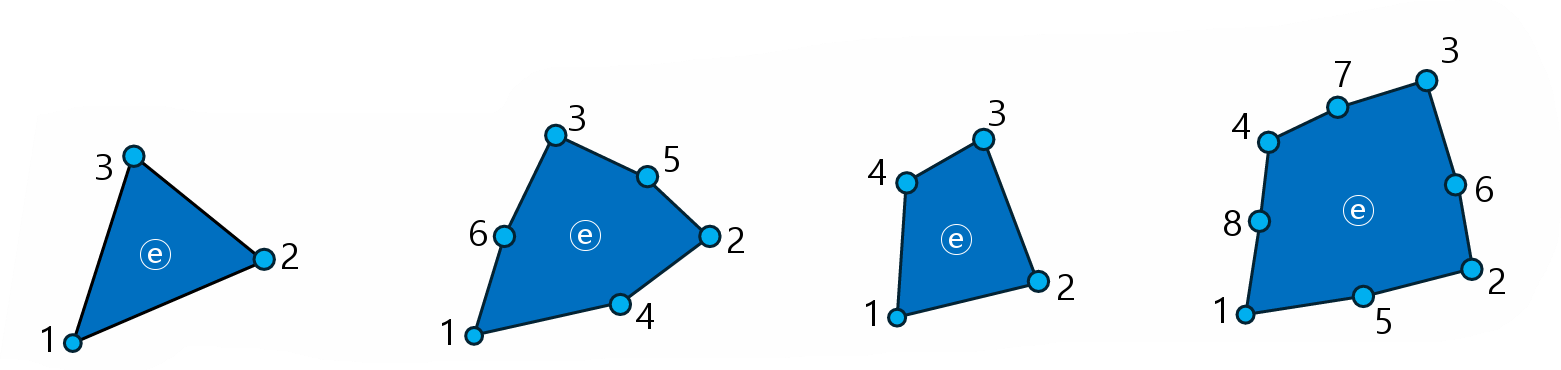
- Two dimensional element
- Triangular type, Quadrilateral type(사변형)
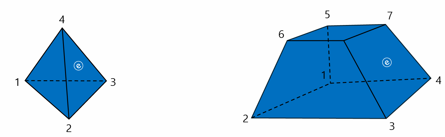
- Three dimensional element
- Tetrahedral type(사면체), Hexahedral type(육면체), 3D solid element
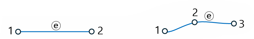
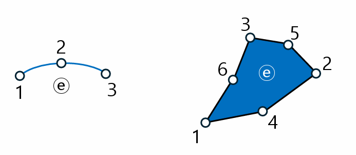
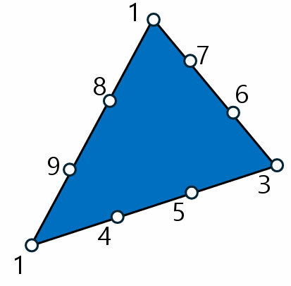
차수(Order, 요소의 절점개수)에 따라 분류하면 다음과 같다.
- 1st order element(1차 요소)
- 한 변에 두개의 절점을 갖는 요소, lineal element(선형요소)
- 2nd order element(2차 요소)
- 한 변에 3개의 절점을 갖는 요소, quadratic element(2차 요소)
- 3rd order element(3차 요소)
- 한 변에 4개의 절점을 갖는 요소, cubic elements
요소 구성 이론을 적용한 특성(Characteristics)에 따라 분류하면 다음과 같다.
- Continuum elements(연속체 요소)
- 비교적 정확한 이론, Continuum Mechanics, Elasticity(탄성론), Solid element
- Structure elements(구조 요소)
- 비교적 근사이론, Solid Mechanics, Structure mechanics, Bar element, Beam element, Plate, Shell
General Producers for Element Analysis
먼저 Nodal points의 coordinates and boundary conditions, Material data, loading data, Element data 등을 입력한다. 그후 ${K}^e {d}^e = {f}^e$(Element Equation,유한요소법의 실제 이론)을 적용한다. 위 식에서 ${K}^e$는 element stiffness matrix(요소의 강성행렬), ${d}^e$는 nodal vector, ${f}^e$는 nodal force vector를 의미한다. 이후 Total System Equation, 즉 Element Equation을 Assembling한다(${K}{D} = {F}$).
댓글남기기